Ant64 Cartridges
The cartridge port is more than a ROM slot. A cartridge can be a passive game ROM, an FPGA personality that turns the Ant64 into another machine, or an active device — its own ESP32, sensors, or radios — talking to the supervisors over the port's SPI, I3C and USB-JTAG lines. This page collects the active-cartridge designs; for the FPGA personalities, see Personality Cartridges.
The Cartridge Port
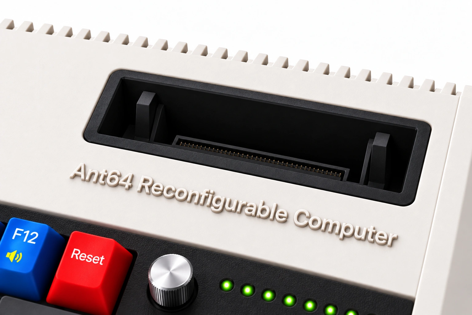
Enclosure concept detail of the cartridge opening and its vertical insertion guides.
A 30-pin edge connector (42 mm, 2.54 mm pitch), hosted by DeMon's CM5. Every cartridge sees the same edge: power, a USB link (C:), DeMon's I²C bus, the Clicky LED data line, and — for service — the CM5's USB-device (rpiboot) flash path:
| Pin | Top | Bottom |
|---|---|---|
| 01 / A | GND | GND |
| 02 / B | 5v | MIPI RX CLK+ |
| 03 / C | Clicky Neopixel RGB LED data | MIPI RX CLK− |
| 04 / D | DeMon I2C1_SDA | GND |
| 05 / E | DeMon I2C1_SCL | MIPI RX D0+ |
| 06 / F | 3v | MIPI RX D0− |
| 07 / G | nRPIBOOT (CM5 GPIO20 / EMMC-DISABLE) | GND |
| 08 / H | GND | MIPI RX D1+ |
| 09 / I | USB D+ (C:) | MIPI RX D1− |
| 10 / J | USB D- (C:) | GND |
| 11 / K | CM5 USB2 D+ (OTG, muxed) | MIPI RX D2+ |
| 12 / L | CM5 USB2 D− (OTG, muxed) | MIPI RX D2− |
| 13 / M | HOST_VBUS (flash-host 5V) | GND |
| 14 / N | USB_FLASH_SEL (mux enable) | MIPI RX D3+ |
| 15 / O | GND | MIPI RX D3− |
- Pins 1, 8, 15, A, D, G, J, M extend further (power-first mating)
Re-flashing the CM5 over USB — the rpiboot device path
The Ant64's DeMon CM5 lite boots its OS from an SD card. To re-image that card from a host PC without pulling it — the "re-image the SD card" recovery floor from the firmware doc — the cartridge port carries the CM5's USB-device (rpiboot) path, the same mechanism the official CM5 IO board exposes on its USB-C slave port. A flasher cartridge (a passthrough to a host PC) uses it to make the board enumerate as a USB mass-storage device and rewrite the SD in place. The board acts as the USB slave; the PC is the host.
Three signals make it work, on the added pins:
nRPIBOOT(CM5 BCM2712 GPIO 20 / EMMC-DISABLE) — pulled low at power-on, it switches the CM5's boot ROM into usbboot mode instead of booting from the card. It must already be asserted when power is applied.- CM5 USB 2.0 D+ / D− — the CM5's OTG-capable USB 2.0, in device mode. In usbboot mode the host runs
rpiboot -d mass-storage-gadget, and the SD appears on the host as a removable drive to write with Raspberry Pi Imager ordd. HOST_VBUS— the flashing host's 5 V. The CM5's OTG uses it to detect the host, and it selects the on-board USB mux (below). (USB_FLASH_SELis an optional explicit override of that mux.)
Getting the USB 2.0 away from the hub. In normal operation the CM5's OTG USB 2.0 feeds the Ant64's internal USB hub (keyboard, mouse, storage). rpiboot needs a direct, point-to-point device connection — a hub in the path stops the host recognising the device. So the mainboard places a USB 2.0 mux on that port: with no HOST_VBUS present it routes the CM5 to the internal hub as usual; when a flasher cartridge presents HOST_VBUS (or asserts USB_FLASH_SEL), the mux swings the CM5's OTG to the cartridge port for a clean link, and the internal hub simply drops off the CM5 for the duration of the flash.
Sequence. Insert the flasher cartridge (it asserts nRPIBOOT and presents HOST_VBUS, so the mux switches) → power the Ant64 → the CM5 comes up in usbboot mode, device-attached to the host → the host runs rpiboot -d mass-storage-gadget → the SD enumerates as USB mass storage → flash it → eject, remove the cartridge, power-cycle → the CM5 boots the freshly-written card.
This path is handled by the CM5's boot ROM before anything else runs, so it works even when AntOS, FireStorm, or the network are dead — it is the deepest DeMon-side recovery short of pulling the card by hand.
Cartridge display input — the spare MIPI RX
When DeMon moved to HDMI it freed one of FireStorm's two MIPI D-PHY RX hardcells. That spare receiver is brought out across the cartridge port's entire bottom row — a 4-lane D-PHY input (clock + D0–D3, up to ~6 Gbps), with a ground between every pair — so an active cartridge can feed a stream into FireStorm the same way Pulse does over its MIPI link, and FireStorm composites it as another display layer. (FireStorm's RX hardcell is 4-lane-capable; the Pulse feed uses two of its lanes, and the cartridge port exposes all four.) To make room and give each pair a clean reference, the redundant bottom-side power/ground is dropped — 5 V, 3 V and GND are all carried on the top row.
That makes the cartridge slot a first-class image source:
- a camera cartridge (MIPI CSI-style sensor) whose frames become a live layer;
- a video / capture cartridge feeding decoded frames in;
- an active co-processor cartridge (its own SoC) that renders a layer — sprites, tilemaps, or finished pixels — and streams it as a Composer-style description or a raw frame;
- anything that already speaks D-PHY, wired straight to the receiver with no bridge chip.
The cartridge is the MIPI TX, FireStorm the RX. It follows the same frame-locked, vsync-paced Composer contract as the supervisor feeds — the cartridge's layer promotes on the system vsync pulse like any other, and it never has to render at full output resolution because FireStorm scales it at scanout.
Signal integrity. Five D-PHY pairs (clock + four data) at up to 1.5 Gbps/lane over a 2.54 mm-pitch edge connector is near the practical ceiling for this contact style — hence the guard grounds: a GND leads every pair, so the clock and D0–D2 are shielded on both sides and D3 on its leading edge (with the top-row GND at pin 15 behind it). The top row carries three grounds too (1, 8, 15); the middle GND at 8 separates the slow signals (power, LED, I²C, nRPIBOOT) on the left from the clustered high-speed USB group (C: USB + OTG USB2 + flash control) on the right, and all eight grounds are the power-first-mating pins. Route the pairs length-matched at ~100 Ω, keep cartridge-side traces short, and be ready to de-rate the rate or use fewer data lanes for a robust link — treat it as best-effort high speed, not a guaranteed 6 Gbps. Watch where the top-side high-speed pairs cross MIPI lanes on the reverse face: C: USB over D1 (position 9), and the OTG USB2 stacked directly over D2 (positions 11–12, a broadside pair-over-pair overlap); a returned-ground guard or a lane-rate drop is the fix if either couples on the bench. In practice the C: and OTG USB are time-exclusive on the port — the OTG is only muxed here during a flash — so their adjacency rarely matters live.